Kite-Lifted 40m End-Fed Activation: Field Deployment & Hard Lessons
A detailed field write-up of a kite-lifted 40 m end-fed on Coochiemudlo Island, including the mechanical setup, RF chain, static bleed, and what changed once the wire stopped sitting still.
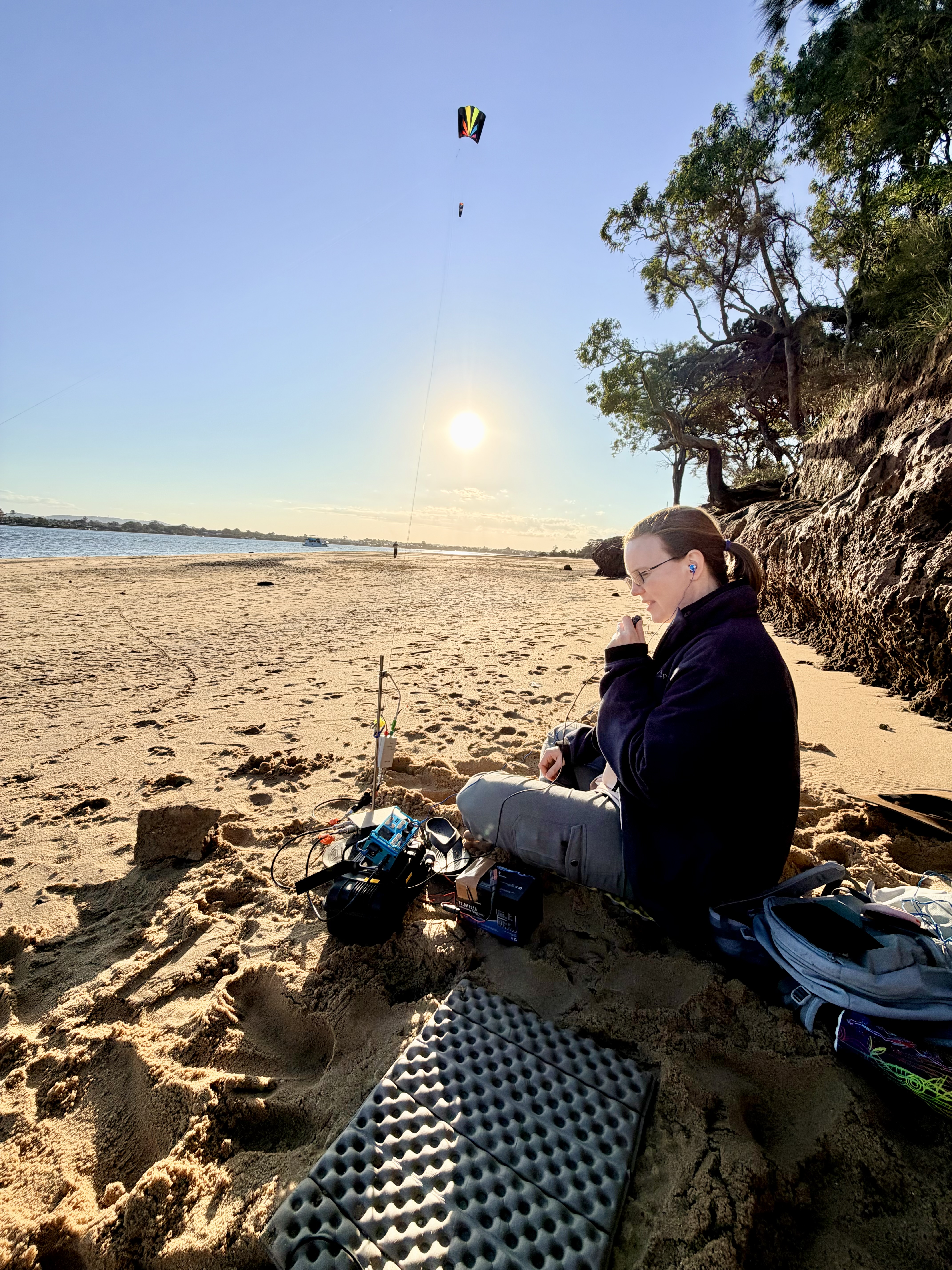
On Sunday 21 September 2025, VK4KLB and I headed out to Main State Beach (AU-8924) at Coochiemudlo to do a two-fer with Moreton Bay Marine Park (AU-7027). It was September in Queensland, so 0600z translated to just after 4 pm local time. Good solid afternoon sea breeze. Enough wind to make the long-standing kite antenna idea feel worth trying for real.
I’ve wanted to hang this 40 m EFHW under a kite for years. Not because it looks cool, though it definitely does, but because I’ve always wondered how much of an antenna’s good behaviour comes from the fact that we force it to sit still. In the backyard this antenna is very predictable. Put it up as a normal sloper and it just works. Put the same wire under a moving kite and all the parts you can normally ignore start mattering very quickly.
Log Summary
These figures combine both park logs for the two-fer, so the total here is higher than the single-log count in the project stats above.
Band breakdown
| Band | QSOs | % |
|---|
Contact rate
Full QSO table (from ADIF)
| UTC | Call | Band | Mode | RST S | RST R | Grid | Ref |
|---|
Why This Was Worth Trying
The fixed version of this antenna is tuned for 7.074 MHz as a sloper from roughly 9 m down to about 2 m. The transformer is a 56:1 autotransformer wound on an FT82-43 with an FT50-43 nested inside, built on the UniBalun PCB from DG1JAN. The wire is insulated SOTABeams. In a normal deployment it sits comfortably under 1.5:1 SWR across the resonant bands and is practically 1:1 on 15 m. It behaves so predictably that you stop thinking about it.
Which made it the perfect candidate to disturb.
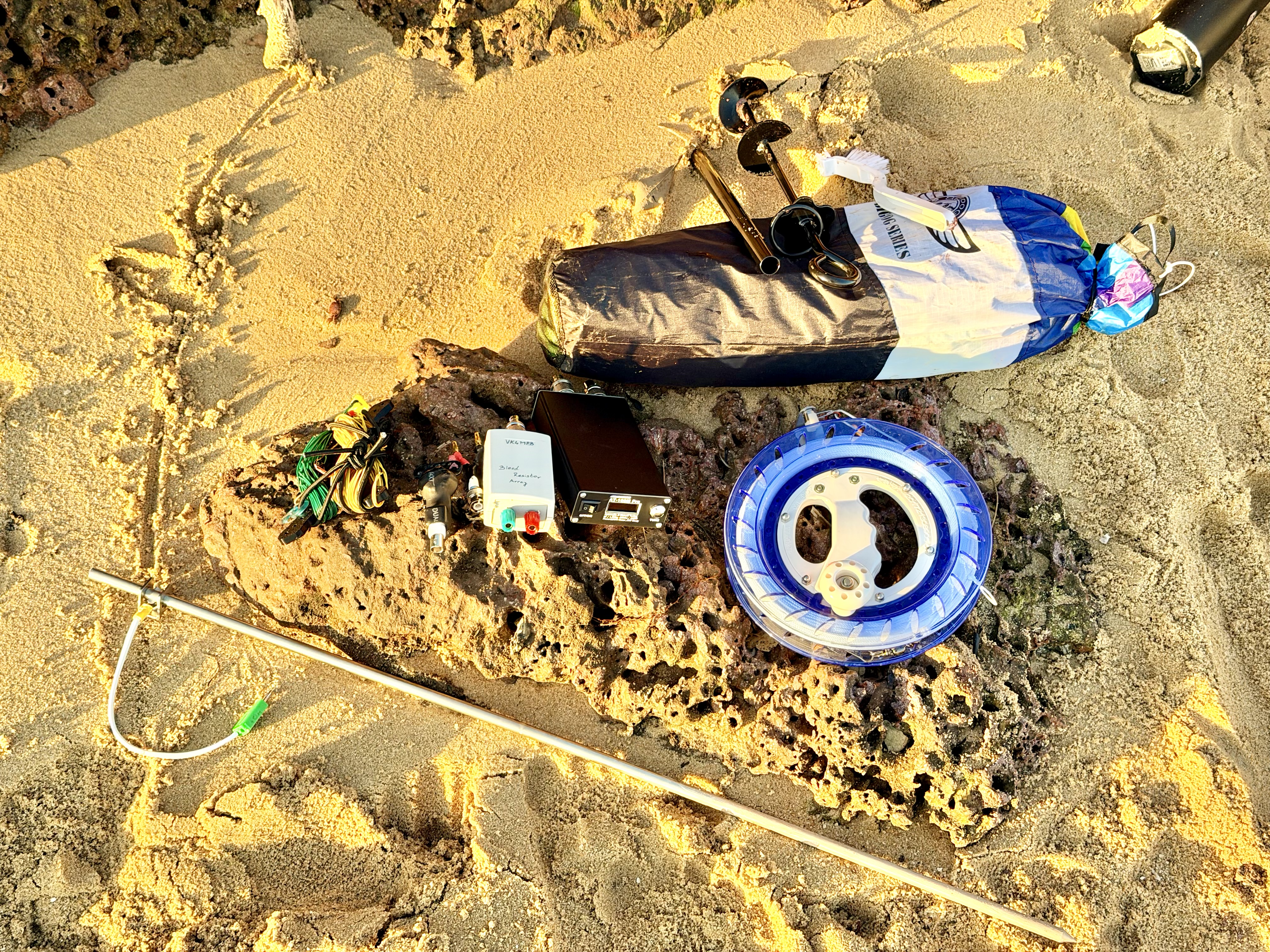
Deployment Geometry
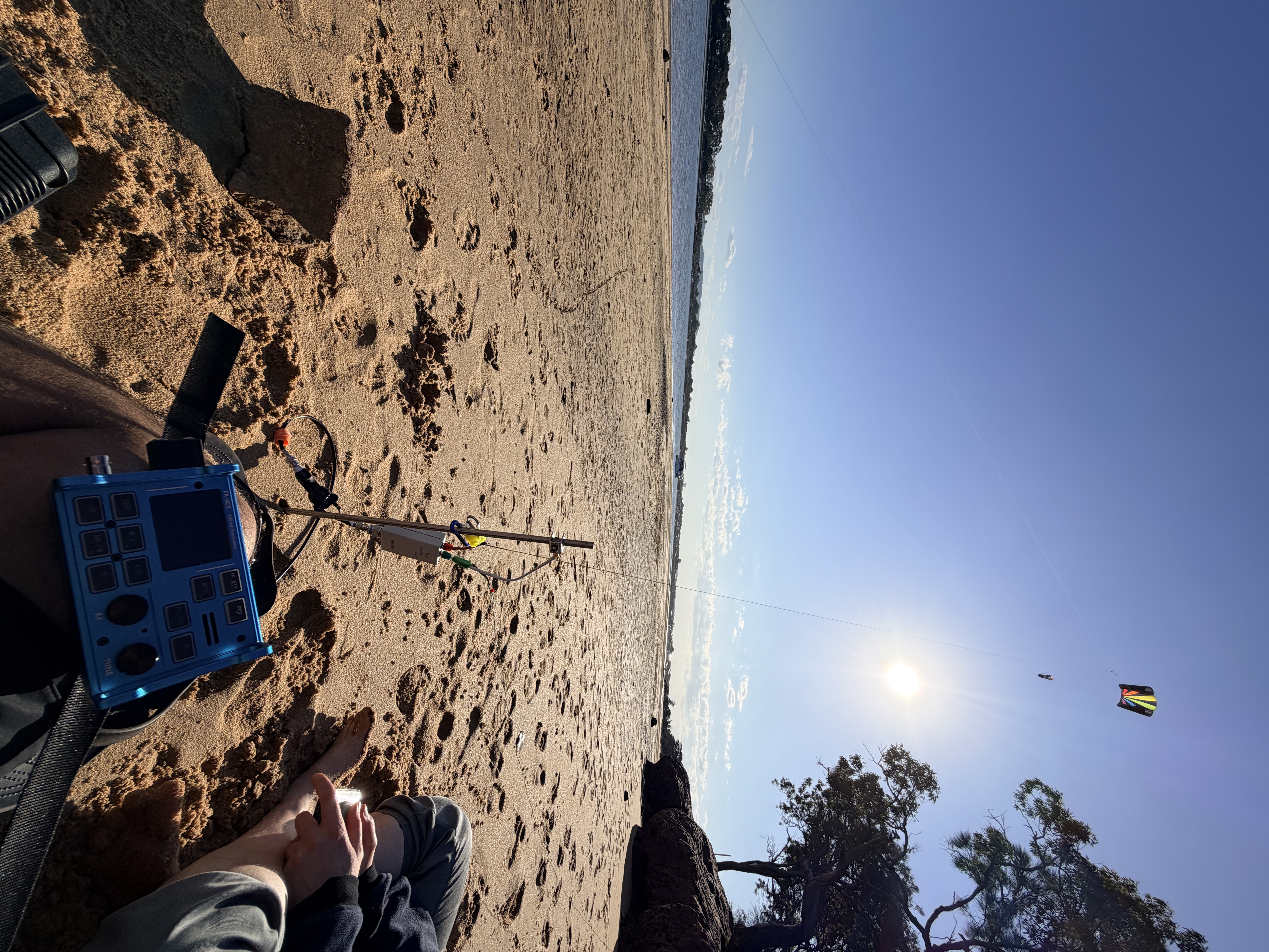
We chose our position carefully, well clear of anyone walking the beach. A long tensioned wire under wind load is not something you casually let drift over people. The Rainbow LS-17.5 Lifter Sled went up cleanly on Dyneema rated for 200 kg. Wind was under 15 kph with gusts below 25 kph — steady rather than erratic — and once it found height the antenna was sitting somewhere around 22 metres above the sand, sloping down toward the operating position.
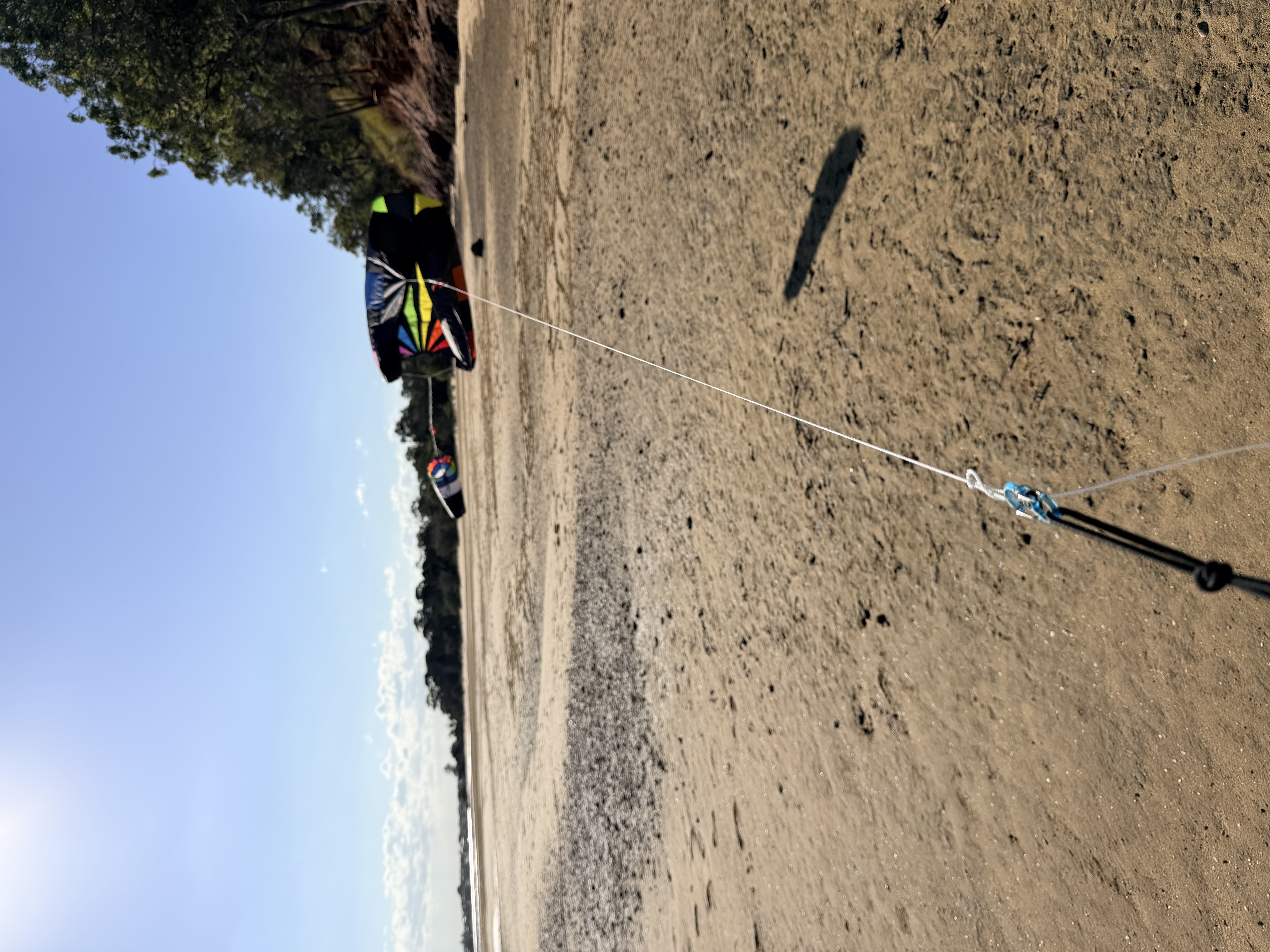
The antenna was tied into a loop in the kite string about two metres below the bridle attachment, with a short section of bungee between the kite line and the antenna wire. That small elastic section mattered far more than it looks on paper. Dyneema does not stretch, and without something to absorb gust energy every change in wind speed would transmit directly into the transformer and connectors. The rope carried the load. The antenna followed the slope. The RF hardware was left to do RF work rather than structural work.
If you build one of these yourself, that is the first design rule I would push hard: do not make your transformer enclosure, studs, or solder joints part of the gust-management system. Let the kite line take the real load. Let the antenna hang. Put something elastic between the two if the wind is going to have opinions.
RF Chain And Static Management
The feedline chain was unchanged from my normal portable configuration. About 5.6 metres of RG58 CU ran from the transformer into a bleed resistor array made from five 1 MΩ resistors in parallel inside a sealed enclosure with SO-239 connectors. From there it passed through a ferrite choke, into the AT-100M Pro tuner, and finally into the FX-4CR. The ground strap from the bleed enclosure to a 1.3 metre steel ground rod was kept under 30 centimetres to keep that path as short as possible. Yes, the rod went into sand. That is what the beach provides.
Static built quickly. At one point I measured over 3 kV on the wire, which is a good way to become very happy that you bothered building the bleed network properly. The resistors did exactly what they were meant to do and nothing made it through to the radio, but seeing that voltage on a moving airborne conductor is a good reminder that wind and long wires generate charge very efficiently.
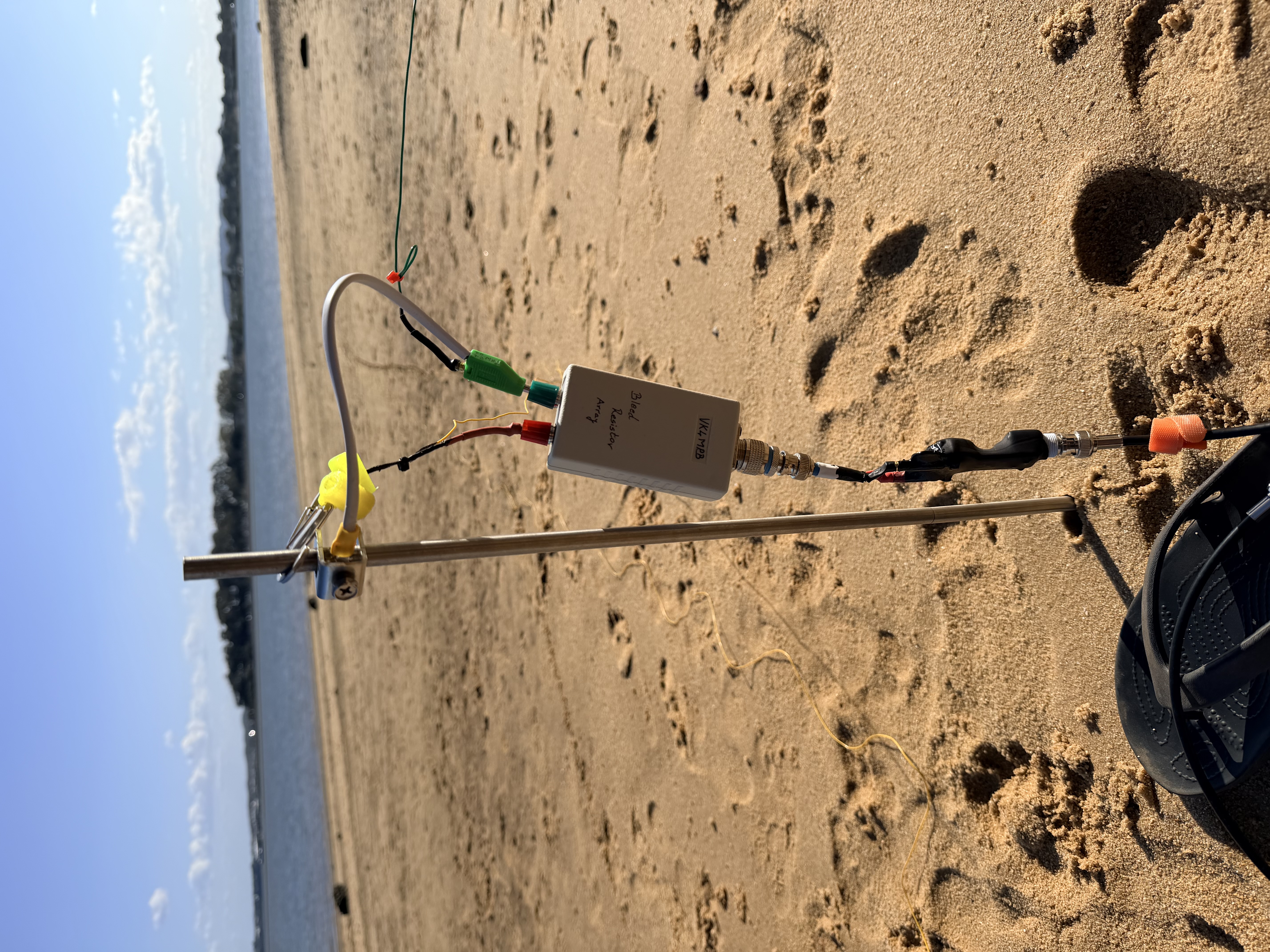
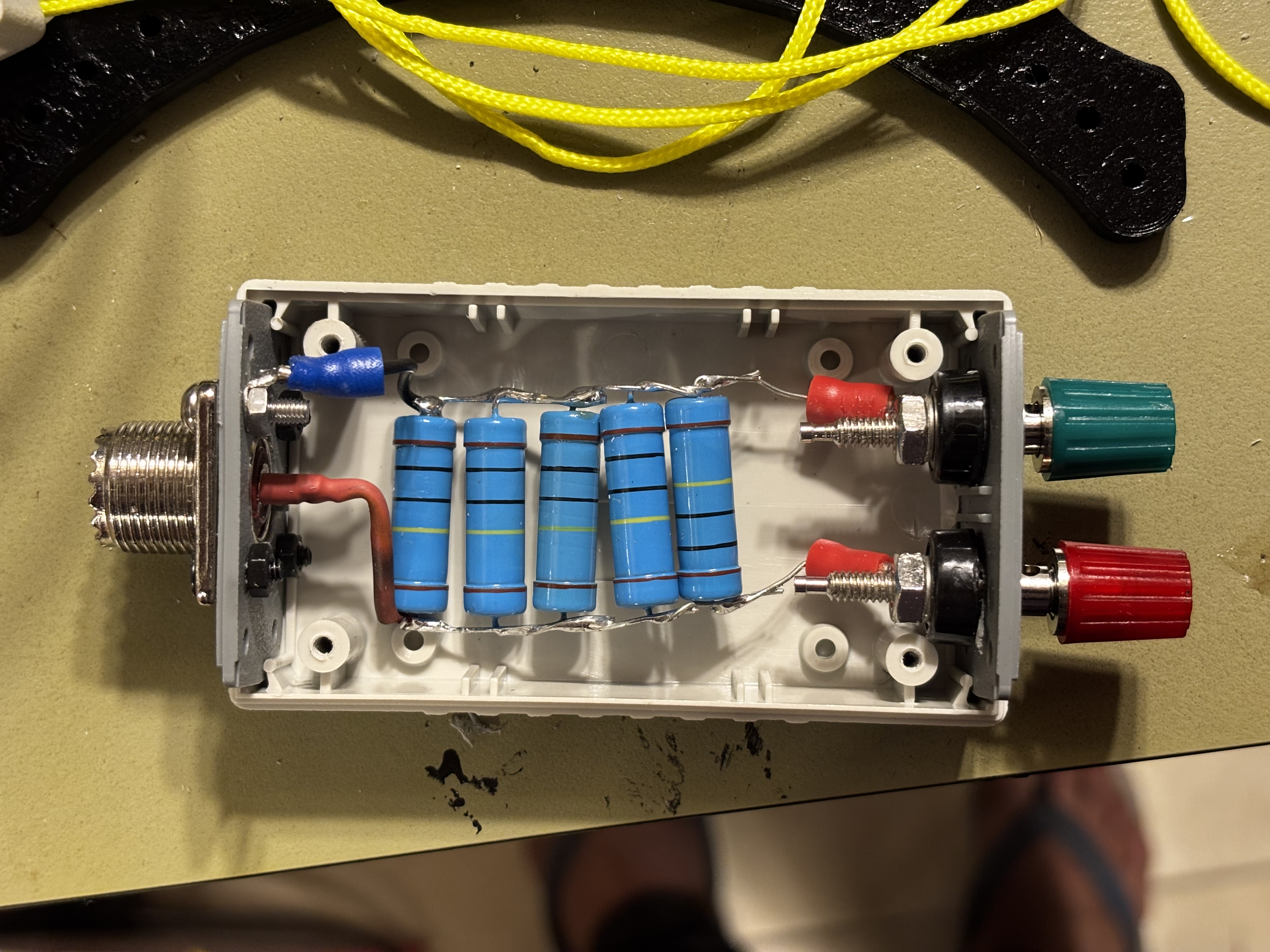
The bleed box is worth spelling out because it is the bit people are most likely to skip until the first unpleasant surprise. A long wire under motion accumulates charge. A long wire under motion on a windy beach accumulates charge very happily. The job of the bleed network was not to make the antenna somehow immune to static. It was to give that charge a path to leak away continuously instead of waiting for a more exciting path through the radio.
Just as important was the ground strap length. Keeping it under 30 cm was deliberate. If the whole job is to get the static away from the radio and into the ground, there is no point giving it a long detour first.
On-Air Behaviour
We started calling at 0601z, just after 4 pm local time. The first entries in the log are VK4DTS and VK4CYA at 06:01:56z, both 59. By 06:05z VK2OKR, VK2BXB and VK2AUS were in the log with 55–56 reports. The band was open and cooperative.
The sloper angle shifted constantly between roughly 60° and 25° as the wind varied, and the SWR reflected that movement. There was no single stable resonant point to admire. The tuner spent the entire activation adjusting to a geometry that refused to stay put. Whenever a gust lifted the kite a few extra metres you could hear the tuner respond, and when the kite dipped the numbers shifted again.
At 06:13:29z F5PYI came in, 59 both ways on 40 metres. From a beach in Moreton Bay into France under a wire that was still moving around in the wind. That was the contact where I looked up at the kite and thought, yep, this was worth doing.
The useful lesson here is that a moving antenna does not have to be a failed antenna. It does mean you stop thinking in terms of one fixed resonant point. The geometry was changing all the time, which meant the tuner was working all the time too. If you try this with no tuner, or with a setup that only behaves when the wire is parked at one exact angle, you are setting yourself up for disappointment.
Failure Mode
VK3PF appears in the log at 06:36:11z, also 59 both ways, and that was the QSO during which the kite came down. It didn’t drift gently; it simply lost lift and returned to the sand mid-contact. The rope took the load as intended and nothing tore out of the transformer. The heavy-duty dog stake anchoring the line had already been vibrating under sustained pull, and when the kite dropped everything relaxed in one go. Almost immediately a dog decided the bright nylon sled was the most interesting object on the beach and ran toward it with enthusiasm that suggested we had provided afternoon entertainment. We retrieved it, reset, and put it back in the air without drama.
What Actually Held Together
The final QSO in the log is at 06:39:00z. From 06:01:56z to 06:39:00z — just over 37 minutes — we logged 42 QSOs across AU-8924 and AU-7027. Despite the continuously changing angle, the wandering SWR, and the brief unscheduled descent, the system kept functioning. The tuner worked continuously, the bleed resistors handled static, the choke prevented RF from coming back into the operating position, and the antenna radiated consistently enough to produce solid reports, including the path into Europe.
Looking back over the log later, what stays with me isn’t a grand lesson about antenna theory. It’s simply that the whole thing behaved like a system rather than a single component. Mechanical decisions mattered. The bleed network mattered. The elasticity in the line mattered. The geometry never stayed the same for more than a few seconds, and yet the radio kept making contacts.
The big takeaway for me was that the antenna only worked as well as it did because the support system, RF chain, static handling, and operating expectations were all built as one system. Take one of those away and it becomes a very different exercise.

If You Want To Try This Yourself
Antenna
- 40 m EFHW tuned for 7.074 MHz (fixed sloper baseline ~9 m to 2 m)
- 56:1 autotransformer
- FT82-43 core with FT50-43 nested inside
- Built on UniBalun PCB (DG1JAN)
- Insulated SOTABeams wire
Radial
- Elevated radial: 7.8 m
- Height: ~1.5–2 m above ground
- Supported independently of the kite system
Feedline & RF Chain
Signal path:
Antenna + elevated radial → Bleed resistor array → Ferrite choke → AT-100M Pro tuner → FX-4CR
- 5.6 m RG58 CU
- Bleed array: 5 × 1 MΩ resistors in parallel (200 kΩ effective)
- Sealed enclosure with SO-239 connectors
- Ground strap < 30 cm
- 1.3 m steel ground rod
Kite & Mechanical
- Rainbow LS-17.5 Lifter Sled (~1.6 m²)
- Dyneema line rated 200 kg
- Antenna tied ~2 m below bridle
- Short bungee section between kite string and antenna
- Heavy-duty dog stake anchor
What to Expect
- Height will vary (ours peaked ~22 m)
- Sloper angle will continuously change
- SWR will move with wind and height
- A capable tuner is essential
- Static accumulation in coastal wind can exceed 3 kV
- Mechanical isolation matters just as much as RF matching
If you decide to build your own, treat it as a full field system, not just an antenna. Work out the load path. Work out the static bleed. Work out what you are going to do when the kite drops, because at some point it probably will. Do that properly and the whole thing works surprisingly well. It just never really sits still.


73 for now, and thanks for the QSOs folks!
VK4MPB / VK7MPB